C2 PROJECT
C2 Photo Album
album:August 2021
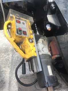
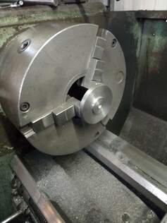
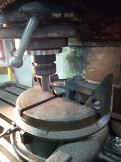
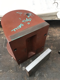
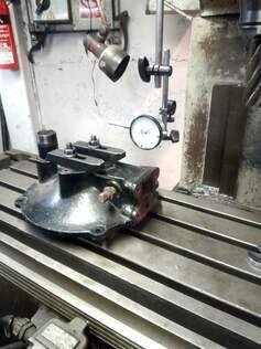
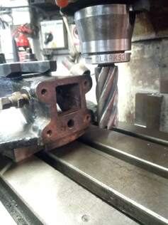
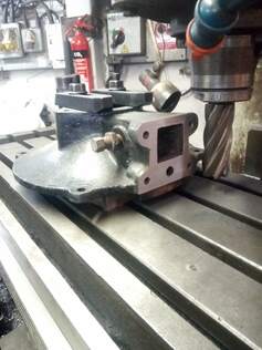
Magnetic base drill set up to drill a hole in the rear bufferbeam. Thanks to Dylan for loaning us the correct tapping drill size.
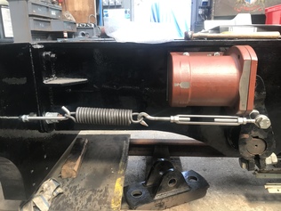
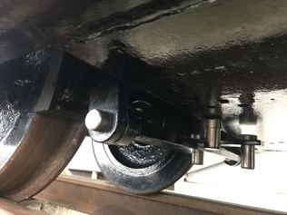
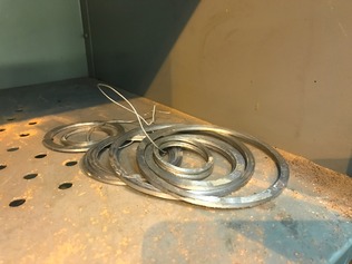
The completed loco steam brake return spring arrangement. The turnbuckle will allow it to be adjusted to the correct setting.
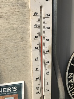
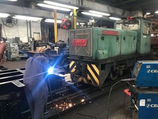
In the C2 shed, this was not a comfortable temperature to be working in.
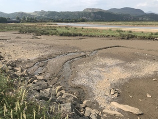
Outside, the river Glaslyn was looking more like a dried-up waterhole in the Serengeti.
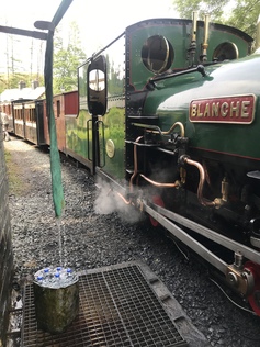
The Tan-y-Bwlch water cooler (bottom left)
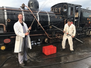
Loco cleaners try to cool off in the heat...
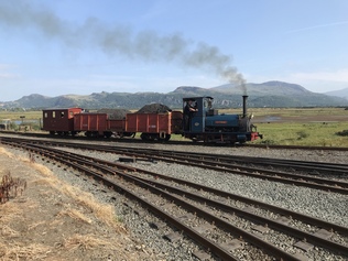
Britomart hauls a short freight train past Boston Lodge in late July. One day, we hope to couple the C2 to a long rake of these bogie wagons for a photo charter...
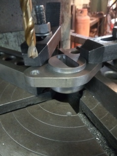
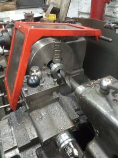
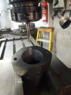
Stages in machining the adjuster cap - on the lathe
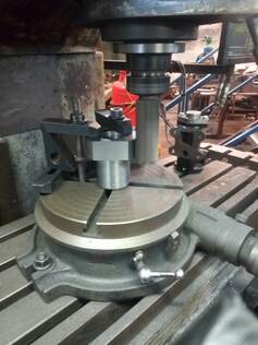
Stages in machining the adjuster cap - on the milling machine
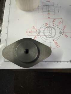
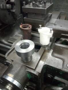
Stages in machining the adjuster cap - trial fit and the original broken part can be seen below.
Stages in machining the adjuster cap - comparison to drawing.
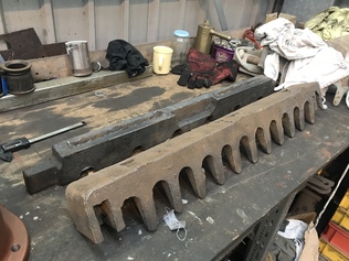
Rocking grate components cleaned up for measuring.
Trial assembly of the tender brake gear over the carriage inspection pit.
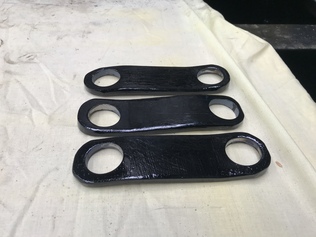
Tender lateral brake links, made from scratch by Helen.
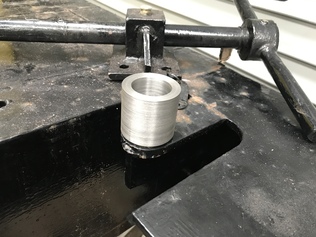
Handbrake column cup, machined by Paul and ready for welding in place.
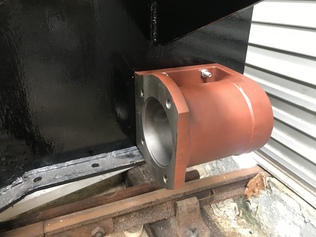
Erle machined a flat on the back of the tender brake cylinder and a thrust block to match.
Tender brake cylinder mounted in position for reaming the holes.
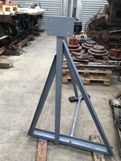
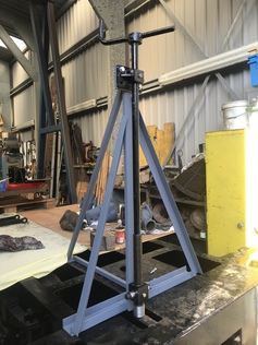
Temporary support frame for the tender handbrake column, made from offcuts by Helen and Paul
Handbrake column in place on the temporary support.
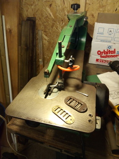
Air inlet guard for the turbogenerator cooling fan, made by Erle using a fretsaw.
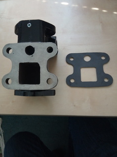
Machining completed on the turbogenerator regulator housing, and Erle has now made some gaskets for the various joint faces.
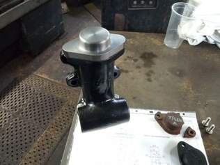
The turbogenerator regulator adjuster cap, machined from solid by Erle to replace a badly damaged original.
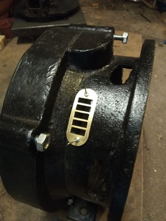
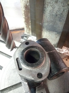
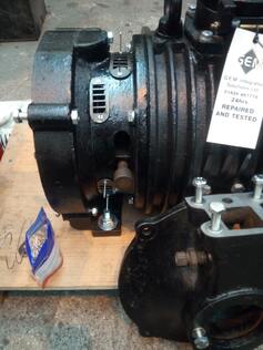
Final machining now completed on the refurbished turbogenerator regulator housing.
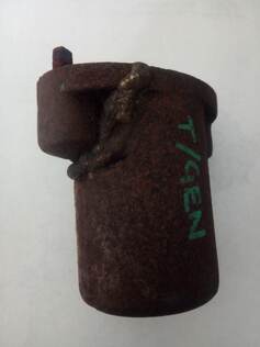
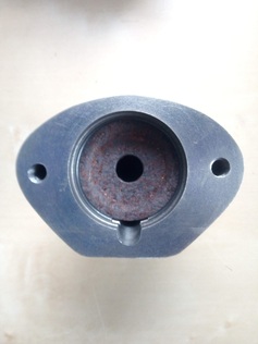
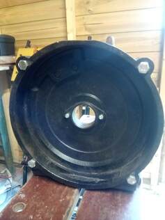
The original turbogenerator piston spring housing, badly cracked and equally badly repaired!
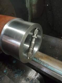
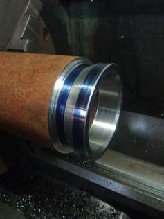
Detail of the various grooves in the turbogenerator piston spring housing. Thanks to Dewi for his advice on machining these.
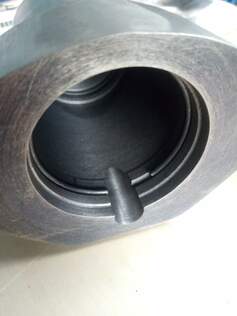
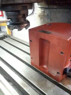
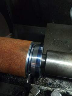
Stages in machining its replacement from solid cast iron (1)
Stages in machining its replacement from solid cast iron (2)
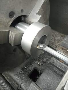
Stages in machining its replacement from solid cast iron (3)
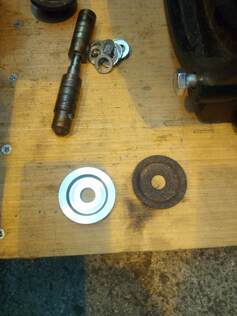
The turbogenerator piston spring housing partly complete, compared to the original and the 3D-printed plastic test piece.
Stages in machining its replacement from solid cast iron (4)
Stages in machining its replacement from solid cast iron (5)
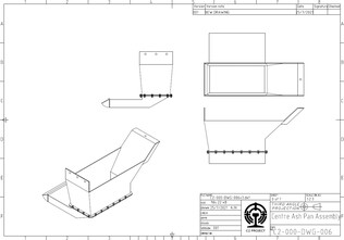
Draft drawing for the central ashpan: following the regauging the ashpan arrangements are rather constrained and this is an option that would suit the current ash disposal arrangements used on the FR.
Andrew welds the tender handbrake column cup into place on top of the tender frame.
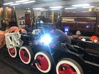
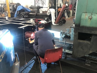
Andrew welds the boiler diaphragm plate bracket on to the loco frames.
A lengthy freight train of bogie wagons formed up for the WHR 'Superpower' weekend. This would look good behind the C2!

Helen presses bushes into the tender brake lateral links.
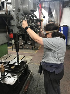
Helen uses the radial arm drill to clean out the holes in the tender brake lateral links.
Motion roller bearing spacers machined by Chris.
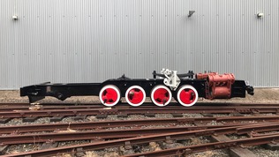
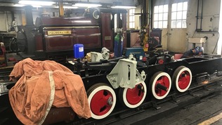
A side view of the loco frames during the shunt moves. Soon this appearance will be significantly changed by the addition of the brake gear, and hopefully the coupling rods not long after.
Andrew welds the steam brake thrust block onto the tender frames.
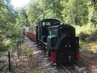
This wasn't in the script! Thunderbird 'Upnor Castle' on a rescue mission driven by Paul. This stalwart 'Planet' diesel was built for the Royal Navy in 1954, and whilst rather basic and noisy it is reliable and ideal for standby duties. Over the years it has had its wheelbase, track gauge, gearbox and engine changed, amongst many other modifications!
Andrew welds the steam brake thrust block onto the loco frames. In the background is 'Palmerston' of 1864, one of the FR's older locos which has seen plenty of use recently on the COVID services.
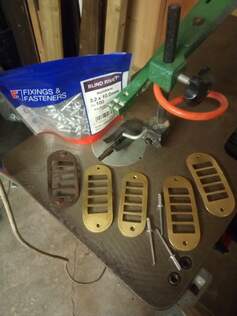
Vent grilles for the turbogenerator, in their natural brass finish.
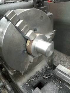
Checking the internal diameter of a bearing spacer sleeve being machined by Erle for the driving axle crankpin.
Turbogenerator regulator piston spring retainer - a new machined component to replace the corroded originial.
The second bearing spacer ready for parting off.
The face where the turbine cover mates with the regulator housing, ready for machining...
...and after skimming flat.
The vent grilles, now chemically blackened and rivetted to the turbogenerator casing.